Since GPS is all-weather, real-time, continuously available, economic and very precise positioning technique, almost unlimited possibilities are opened up for its use in geodesy, surveying, navigation and related fields, including
- control surveys
- cadastral surveying
- geodynamics
- monitoring and engineering problems
- precision navigation
- Photogrammetry
- marine and glacial geodesy
1. Geodetic Control Surveys
For geodetic control with GPS the following objectives can be identified:
- Setting up of a completely new field of control points
- Densification or extension of existing network
- Inspection, analysis, and improvement of existing networks
- Contribution to the determination of height and geoid
The installation of a completely new network can be performed in three steps
Level A: Continental (or sub-continental) Reference Frames
Level B: National Fundamental Networks
Level C: All other GPS measurements
At level A, a continental or sub-continental GPS Network is installed, with ITRF / IGS Sites as known stations.
ITRF = IERS Terrestrial Reference Frame
IERS = International Earth Rotation Service
IGS = International GPS for Geodynamics Service
The station coordinates of ITRF / IGS Sites are accurate to about 0.1m or better.
The inter-station distance is 300Km to 500Km. The station coordinates have to be determined with highest achievable accuracy e.g. ± 1cm. This is possible with about 1 week of observation, dual frequency receivers, precise orbit and advance software. At level B, nationwide, or state-wide fundamental networks are installed with a spacing of 50 to 100Km, depending on the size of country and the objectives. The stations of step A are kept fixed as known points. The accuracy of the individual GPS station with respect to neighbouring stations is again ± 1cm, hence providing a homogeneous set of coordinates for the whole country.
At level C, all other GPS measurements have to be connected to stations of step B, again at the 1cm level. One advantage when compared with classical techniques is that no systematic densification is necessary. Work can be done, following a priority schedule, where coordinates are required.
The densification of an existing network can be treated in different ways:
- A precise classical terrestrial network of 2nd or 3rd order exists: In this case GPS is used as a modern Surveying Tool for precise network densification. GPS is in nearly all cases much more economical than classical methods. The existing trigonometric control points are taken as fixed reference stations. This approach is used in many countries as a tool for rapidly providing precise geodetic control.
- A terrestrial network of medium or low accuracy exists; the old coordinates shall be maintained: In this case the distortion of the network is introduced into the precise GPS results. GPS is only used as a method of cost effective interpolation into the existing national framework. The GPS observations should be preserved for a rigorous adjustment once a fundamental GPS network has been established in the area at some later date. This procedure is acceptable as an intermediate solution, in particular in developing countries until a completely new network and datum, based on satellite techniques, can be established.
- The existing terrestrial network is combined with new GPS observations: In this case the existing network on a datum is maintained; however the complete network is readjusted and strengthened with the inclusion of GPS measurements. New points are linked to the existing network in an optional way. All network coordinates are slightly changed. This method only works if sufficient stochastic information on existing network is available.
- The analysis of an existing network: The analysis of an existing network is of particular importance in countries where little information on the original observation and computation is available. This is in particularly true for some developing countries. The analysis, however, also offer a very important insight into the existing official networks of countries with an advanced cartographic tradition, such as in Germany. For the analysis a certain number of existing stations is re-occupied with GPS. The residuals after a seven-parameter transformation are inspected.
2. Determination of Heights and Geoid
GPS yields 3-D coordinates that can be transformed into ellipsoidal longitude l , latitude f, and height h. The vertical component is particularly sensitive to the geometrical configuration of the GPS satellites and to the unmodelled error in atmospheric refraction. Simulation studies show that the error in the vertical component is about twice as high as in the horizontal components. Experiences from field tests and comparisons with precise terrestrial control often yield about the same accuracy in all three coordinates. GPS is hence a powerful means for precise height determination. Considering the error budget, only height differences are of interest. It is obvious that the ellipsoidal height h, coming from a GPS solution, is a purely geometric quantity. For most practical purposes, heights related to the gravity field rather than to the ellipsoidal are required.
The relation between h (Ellipsoidal Height from GPS observations),
H (Ortho-metric height from spirit levelling) and
N (Geoid height from a geoid computation) can be written according to figure 1.
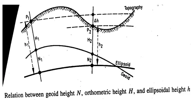
Figure 1: Relation between geoid height N, orthometric height H and ellipsoidal height h
If two types of information are known, the third one can be determined, i.e.
- With precise geoidal heights the orthometric heights can be derived from GPS in order to control or to substitute sprit levelling.
- With precise levelling information and ellipsoidal heights from GPS the geoid can be determined or controlled.
The repeated determination of GPS heights is completely sufficient if only height changes have to be analyzed. Hence, three basic applications of GPS height determination can be identified
- Height changes from repeated GPS control
- Transfer of orthometric heights with known Geoid
- Determination of Geoid
Height changes are mainly of interest for engineering purposes or vertical Crustal movements.
The determination of orthometric heights is a long term goal in order to substitute time consuming and expensive spirit levelling. Assuming simple error propagation laws, on a GPS traverse one can expect a height transfer accuracy of about 0.1m over several thousand kilometres. This estimate has been verified over a 3000Km Geoid traverse in Northern Europe.
Where heights in the gravity field are known from levelling lines it is possible to derive, directly geoid heights from GPS results. This method can contribute considerably to the rapid determination of precise geoids. Several dedicated geoid-GPS campaigns have been performed throughout the world. One major problem to be solved with GPS heights is the connection of separated tide gauges and establishment of a global height datum. This includes the determination of a precise marine geoid and of the sea surface topography.
One very important aspect of the use of GPS for heights is that errors in the absolute position of a reference station propagate into the ellipsoidal height differences. As a thumb rule, a position error of 10 meters may cause an error in the ellipsoidal height difference up to 2ppm.
3. Cadastral Surveying, Geographic Information System
Because of the high accuracy in connection with short observation time, GPS can also be employed economically for network densification over very small distances ( 1 Km to 10 Km).
One major problem in usage of GPS in Cadastral Surveying is signal shadow caused by buildings, trees, towers, bridges etc. This is why the exclusive use of GPS in cadastral surveying will be restricted to open areas. With the presence of such obstructions, GPS will be mainly used to determine rapidly the standpoints for electronic tachometers or other conventional surveying instruments.
In cases of free sight like the most rural areas, or also in urban areas with broad streets, low buildings and low vegetation, the rapid GPS methods can be used with advantage. Semi kinematic methods are advisable in the complete absence of obstacles. Otherwise the rapid static methods should be employed. Depending on the accuracy requirements, GPS provides continuous position information in all scales of interest. GPS is also powerful means to support Geographic Information System (GIS). The role of GPS is
- It contributes to a uniform basic geometric frame, for example a coordinate system, a digital map, or a digital terrain model.
- It contributes to geometric locations of objects that enter the GIS, e.g. streets, buildings, power lines, property boundaries.
- It allows GIS to be taken out into the field with GPS direct-entry.
- It forms an integrated building-block in a command and control system e.g. for moving vehicles, or machines that are navigating based on a digital terrain model. Depending on the accuracy requirements, GPS provides continuous position information in all scales of interest.
4. Geodynamics
The very high accuracy potential associated with comparatively easily transportable equipment makes GPS a suitable technique for determining recent Crustal movements.
Until recently, Crustal movements were mainly analyzed with very long base line Interferometry (VLBI) and Satellite Laser Ranging (SLR). With VLB1, long range baselines can be determined precisely, a few centimetres over several thousand kilometres are achievable.
The main disadvantage of the VLBI method is the enormous technical expenditure and the limitation to a comparatively small number of fundamental stations. Only very few transportable systems are available. With Satellite Laser instruments very precise and reliable movement rates have been derived from many years observation.
Transportable Satellite Laser Ranging systems are also in use still, the use of SLR technology involves high costs and long mobilization times. For many areas of interest, in particular if large numbers of points are to be determined at not too great spacing, GPS offers considerable advantages. When planning operations for the determination of Crustal movements it must be considered that with GPS techniques a relative accuracy of 1.10-6 to 1.10-7 of the point distance can be achieved operationally. For a 100Km baseline, this corresponds to 10 to 1cm, and for a 1000Km baseline, 100 to 10cm.
In view of the known motion rates of a few cm/year or only mm/year, the station spacing should not be much greater than 100Km. For large distances, highly sophisticated observations and evaluation techniques have to be applied that provide a relative accuracy of a few parts in 108 . The most important limiting factors in the error budget are
- orbit accuracy
- Modelling of atmospheric refraction
To achieve a relative accuracy of 1.10-7 the orbit must be determined to within ± 2cm. The broadcast orbits are more than ten times less accurate. To achieve the necessary orbit accuracy one must either make use of precise ephemeredes calculated at a later date, or simultaneous observation must be made during a project at precisely known reference stations to enable orbit improvement or orbit recomputation over the working area. This last-mentioned approach is also called the fiducial station concept. The fiducial stations should be known with centimetre accuracy, for example for SLR or VLBI observations. The individual dislocation of the control points, caused by global and regional plate motions, or by local effects, have to be regularly monitored. Well suited fiducial stations are the ITRF Sites and the stations of the forthcoming International Geodynamics / GPS Service (IGS).
Many of the areas with tectonic activities are located in regions with high ionospheric disturbances, near the geomagnetic equator or in high latitudes. In such case the use of dual frequency P-code receivers is essential. Long observation periods over at least 24 hours help to average out residual effects.
The following main fields of application for Crustal motion monitoring can be identified.
- Global and continental plate motion and deformation analysis.
- Regional Crustal motion analysis
- Local monitoring of deformation and subsidence.
Project of group (a) are still in the conceptual and validation phase. Comparison between GPS and VLBI results over up to 2000Km show an agreement on the 1s level, and hence prove in principle the capability of GPS for global dynamics.
Projects of group (b) already shown significant results. Investigation and first epoch measurements have been started in nearly all parts of the world with tectonic activities. Usually displacement vectors are derived from the comparison of two or more epoch measurements.
One major difficulty in the analysis of a displacement field is the identification of stable reference points. Powerful methods have been developed in the field of network deformation analysis to address this problem.
In areas of high risk (e.g. earthquake, volcanic eruption) like the San Andreas Fault in California or the Kanto – Tokai region of Japan, continuously monitoring GPS arrays have been installed. Even in Survey of India three GPS permanent stations have been installed at Bhubaneswar, Pune and Thiruvananthapurum. Survey of India has the plan to establish 27 such GPS stations all over the country.
Project of group (c) i.e. monitoring of local deformation in most cases belong to the field of deformation analysis in engineering surveying possible applications are the monitoring of
- Land subsidence e.g. in mining areas and soil fields
- Land sliding
- Local Geo-tectonic
In most cases the point distances are very small (about 1Km), hence an accuracy of a few millimetres can be achieved, and very small deformations can be detected. Depending on the objectives of the control, and the expected rate of motion, the measurements have to be repeated after a given time period, e.g. days, weeks, or months. At least one stable reference station is required.
A new and very promising field of GPS application in geodynamics is earth Orientation Monitoring, in particular the variation of UT, and Polar Motion. Error analysis and comparison with other space techniques demonstrate the high potential of GPS in monitoring daily variations at the accuracy level of a few centimetres. Earth rotation monitoring, together with the establishment of a precise global reference frame, will be one of the major objectives of the forthcoming International Geodynamics GPS Service (IGS).
5. Engineering and Monitoring
Almost unlimited possible uses and applications may be conceived in this field. Some fields of Applications are:
- Determination of Geodetic Control points for
- Cartography
- Geographic Information System (GIS)
- Photogrammetry
- Geophysical Surveys
- Inertial Surveys
- Antenna location in hydrographic surveying
- Expeditions of all kinds
- Archaeological Mapping
2. Monitoring Object Movements by repeated or continuous measurements
- Ground Subsidence
- Land Sliding
- Construction of dams
- Subsidence of offshore structure
- Settlement of buildings
3. Setting out local networks for the control of engineering projects
- Tunnel Construction
- Bridge and Road Construction
- Pipe lines etc.
- Water ways
4. Real time guidance and control of vehicles
- Construction vehicles
- Large excavators in open mining
- Forklifts in open storage area (e.g. container yards)
If two antennas and receivers are used, GPS can also be employed as a method of determining directions. Due to this advantage of GPS it can be used
- for control network for tunnel construction
- network for dam control
The advantage of GPS can in particular be demonstrated for the tunnel network. The main purpose of such a network in the setting out of the bearing of the shaft centre line at both entrances, PW (Portal West), and PE (Portal East). In classical engineering, both portals had to be connected via a precise network, covering the whole area. This could be extremely difficult task in mountainous or thickly forested area. With GPS it is sufficient to determine two control points each at both entrances for setting out the bearing of the central line. For security reasons, it is advisable to establish a second target pillar at each portal for reference bearings. The distance should not be too large to enable sights under unfavourable atmospheric conditions.
The relative location of the two portal networks can be determined with an accuracy level below 1cm for distance up to 10Km. In order to provide level heights via GPS, it is necessary to include a precise local geoid computation.
The second example refers to the Permanent Control of a dam under construction and after completion.
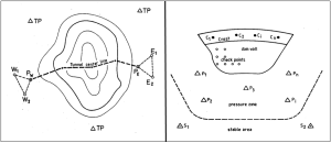
Figure 2: Dam Control with GPS
A difficult task is the selection of stable control points, and delimitation of the pressure zone from the stable area. Usually the advice and support of experts is required. One advantage of GPS is that the stable control points Si can be placed far enough from the influence zone, and that no direct sight connection to the near-construction control points Pi is required. GPS can be used to
- establish stable control point (Si)
- establish and monitor control points in the pressure zone (Pi)
- establish control point on the dam crest (Ci)
Check points attached to the dam wall remains to be controlled by other techniques, either by electric tachometers or by EDM. Regarding the high potential of GPS concerning accuracy and cost-effectiveness, it is possible to install a dense network of control points in the potential pressure zone.
Deformation can be derived from repeated observation, in intervals of days, weeks, or months, depending on the situation. In case where there is suspicion of impending structural distress, the establishment of a continuous monitoring array can be taken into consideration.
One critical factor is the limited visibility for stations near the dam wall. The full constellation of GPS satellite is available and at least 4 satellites are visible at any time to serve the purpose. But the drawbacks are the unbalanced geometry and multi path effects. Instead, control points near the dam wall can be related to better placed control points by EDM or Total Stations.
6. Precise Navigation, Marine Geodesy and Hydrography
Because of the real-time capability, continuous availability and the high accuracy potential, this field of use is very broad, is still growing, and is developing fast.
The possible applications and the related accuracy requirements can be divided into three user groups.
- low accuracy requirements, about 100m in position, and 1m/sec in velocity
- medium accuracy requirements, about 1 to 10m in position, and 0.1m/sec in velocity
- high accuracy requirements, better than 0.1m in position and height, and 0.01m/sec in velocity.
A user inquiry in 1990 indicated highest interest in the group (b), i.e. a position requirement of few meters. User group (a) can be satisfied with a single C/A code navigation receiver aboard a ship, even under selective availability (SA). With the full satellite constellation in orbit, GPS will provide continuously two dimensional position accuracy of ± 100m in the standard positioning service (SPS) ± 10-20m in the Precise Positioning Service (PPS) (for authorised user only). If S. A. is not activated, a single C/A code receiver can provide an accuracy of about ± 30m.
The above mentioned accuracies suffice for many tasks in the Marine environment. Important areas of employment in user group (a) are, for example
- general navigation task on the high seas
- research in Oceanography
- ships position in small scale bathymetry with swath systems
- Position and velocity in small scale gravimetric, magnetic, and seismic measurements.
For some applications of task (3) and (4), the accuracy of a single operating receiver is not sufficient under activated S. A. In this case, and for the majority of applications (user group (b)) in marine geodesy, hydrography and precise navigation GPS must be operated in the relative mode (Differential GPS (DGPS)), i.e. reference observations have to be carried out at known (usually stable) stations on the coast, on islands, or fixed marine structures.
If precise positions are required in real-time, so called differential corrections have to be transmitted to the user. To be independent of the particular selection of satellites it is advisable to use range corrections rather than position corrections. The reference stations tracks all visible satellites and generate range corrections; the remote vessel uses range corrections only for the satellites that are tracked by the vessel receiver.
Position corrections that are derived from a non-identical satellite constellation under SA may introduce systematic error of more than 10m.
The format of differential corrections have been standardized by the Radio Technical Committee for Marine Services (RTCM) and has a data rate of 50 bits per second.
Relative observations can be either organized for the individual task under the responsibility of the Project Management, or they are based on a continuously available governmental or commercial service. With the developing requirement of precise navigation, the establishment of permanent reference array will evolve. Some DGPS services are already working, or in the definite planning phase, in particular in the areas with heavy sea traffic or off-shore activities, for example in the Gulf of Mexico, or the North sea.
Typical fields of application in user group (b) are for example –
- precise navigation in coastal water
- harbour approach
- Sea bottom mapping in the Exclusive Economic Zone (EEZ) or for scientific purpose.
- Hydrography
- Precise gravimetric and seismic surveys
- Positioning of underwater sensors and samplers in Marine prospecting for mineral resources.
In case where the data are not required in real-time, the final position can be computed afterwards (post-mission) in a post processing step. However, considering huge amount of data it is advisable to determine the ship’s position in real-time and not to store the original raw data.
A further option of the differential mode is to use the carrier phase data at the remote station to smooth the code phase observations with and appropriate filter algorithm. This method works on a routine basis if an appropriate receiver is used, and provides a continuous accuracy of 2-3m for the moving antenna.
An increasing user market requires an accuracy level of better than 0.1m (user group (c)). In this case the carrier phase observable has to be used as the primary quantity and the ambiguities have to be resolved. The pure kinematic method with ambiguity resolution techniques `on the way’ has to be applied. For real-time application the whole data stream has to be transmitted from the reference station to the moving user via data link with 2000 to 3000 baud (bit per second) capacity, and the onboard processor has to accept data simultaneously from at least two receivers.
Possible applications in user group (c) are –
- Precise hydrographic surveying.
- Monitoring silt accretion and erosion in rivers, lakes, estuaries coastal water and harbor areas.
- Real-time dredge guidance and control.
- Support of coastal engineering.
- Marine geodynamics.
- Precise continuous height control.
- Altitude control of ships, buoy and floating platforms.
For precise echo-sounding and sea level monitoring a continuous height determination of a few centimetres is required. With three antennas / receivers on board a ship the time-dependent spatial behaviour of the platform can be monitored in real-time. Experiments have demonstrated a resolution of ± 0.01° in azimuth, 0.25m rad / 345 in pitch and rol1, and 1cm in ship’s deformation.
Note that most developments in precise marine navigation with GPS can easily be applied inland navigation and remote vehicle control.
7. Photogrammetry and Remote Sensing
The use of GPS contributes in several different ways
- determination of ground control points
- navigation of photogrammetric aero planes
- determination of sensor platform coordinates and orientation
The determination of ground control points (group (a)] for photogrammetric map production can be done in similar fashion as in geodetic control. The techniques and efforts required depend on the desired map scale. For cadastral purposes centimetre accuracy can be achieved with carrier phase adjustment.
The accuracy requirements are much less for control points and ground twisting in satellite images (e.g. SPOT, LANDSAT). The level of1to 5m can be achieved by differential technique using code or carrier smoothed code observation only, without resolving ambiguities. The remote receiver can be operated over distances up to several hundred kilometres. It is sufficient to collect only a few minutes of data on the site. It is, however, to use identical satellite for both stations in the relative solution, otherwise error of 10m or more can be introduced under S. A.
For the precise navigation (group (b) of Survey aircraft the differential mode and a real time data link is required. Usually the transmission of range corrections is sufficient to assure an accuracy of better than 10m, as long as at least four satellites are visible.
The most promising contribution of GPS to Photogrammetry is the determination of the sensor orientation, in particular the precise camera position (group c) in order to support aerial triangulation. GPS determined camera positions are introduced as precise observations into the combined block adjustment. As a consequence the required number of ground control points can be reduced to about 10%, or even less, of those required in conventional aero triangulation.
In order to achieve the required accuracy level of about ± 5cm it is necessary to
- operate in differential mode
- use code and carrier phase data
- Resolve the phase ambiguities.
A serious problem of signal loss occurs from some of the satellites due to inclination of the aircraft while turning. If less than four satellites are visible, a new cycle ambiguity has to be determined.
The benefit of GPS to Photogrammetry has been demonstrated in various experiments. The aero triangulation works out properly with no more than four control points per block whilst under certain circumstances even one control point can be sufficient. The method is hence very effective in areas where ground access is difficult or impossible. The use of GPS on orbital platforms for remote sensing purposes is under consideration since 1993.
8. Special Application of GPS:
As stated above the possible applications of GPS in the field of engineering and geosciences are unlimited. Some further examples are –
- Railroad corridor surveying
- Navigation of vehicles for improving agriculture productivity and seed control
- Installation of a highway inventory
- Forest management
- Vehicle tracking
Further consideration is here given to –
- Glacial geodesy
- Time transfer
- GPS carrying satellites
In Glacial Geodesy and Antarctic Research GPS can be employed successfully to determine the movement of glacial or Ice sheets. If motion parameters (velocity and azimuth) are to be derived from repeated measurements over the years, a quasi-online reading suffices, while a route is traversed with snow mobiles, or a helicopter lands for a short time. In the relative mode to a fixed station, sub-decimetre accuracy can be attained with observation times £ 1 hour (depending on the distance), so that correct results can be expected from repeated measurements after about 1 month in the same season.
GPS is one of the most efficient means for operational global clock synchronization on the order of magnitude of 10 nanoseconds. The one nanosecond level for continental distances seems to be achievable. In most cases the so called common view technique is applied. The time of arrival of the same signals from one satellite is observed at two stations and compared with the local reference clocks. The signal travel time between the satellite and the station has to be calculated, based on the precise coordinates for both stations and the satellite in the same reference system (WGS-84).
A station position error of 30cm enters with 1 nanosecond into the error budget.
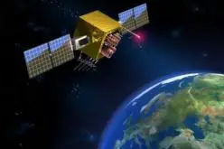
Very powerful GPS earth science applications result from the deployment of GPS sensors on near earth orbiting satellites. The GPS data received at the orbiting platform may serve for
- Precise position determination of remote sensing satellites, primarily of altimeter satellites.
- Precise position and orbit determination of satellites, probing the earth’s gravity field.
- Analysis of GPS signals after passing the high atmosphere i.e. ionosphere, troposphere.
Read related article:
- Introduction to GPS
- Fundamentals of GPS Signal And Data
- GPS Surveying Techniques
- GPS Field Observation and Data Processing