
1. Introduction
- The Total station is designed for measuring of slant distances, horizontal and vertical angles and elevations in topographic and geodetic works, tachometric surveys, as well as for solution of application geodetic tasks. The measurement results can be recorded into the internal memory and transferred to a personal computer interface.
- The basic properties are unsurpassed range, speed and accuracy of measurements. Total stations are developed in view of the maximal convenience of work of the user. High-efficiency electronic tachometers are intended for the decision
It has the broad audience for sole of industrial problems. - Angles and distances are measured from the total station to points under survey, and the coordinates (X, Y, and Z or northing, easting and elevation) of surveyed points relative to the total station position are calculated using trigonometry and triangulation.
- Data can be downloaded from the total station to a computer and application software used to compute results and generate a map of the surveyed area.
- A total station is an electronic/optical instrument used in modern surveying. It is also used by archaeologists to record excavations as well as by police, crime scene investigators, private accident Reconstructionists and insurance companies to take measurements of scenes. The total station is an electronic theodolite (transit) integrated with an electronic distance meter (EDM), plus internal data storage and/or external data collector.
- The purpose of any survey is to prepare maps, control points formed a basic requirement for the preparation of these maps.
- There are several numbers of methods like traverse, triangulation etc., to provide these control points.
- Whatever the method the provision of control points, includes the measurement of two entities( Distance and Angle).
- Again, distance can be measured by using various instruments like chain, tape.
- Linear Tap.
- Gunter’s chain (20m and 30m).
- Steel band(20m and 30m).
- Inver tap.
- Hunter Short Base (80m).
- Electronic Distance Measurement Instruments, Total station and GPS.
- Angle can be measured by using a THEODOLITE.
- Once distance and angular measurement is over computation is performed to provide the control points. A combination of all the three results in a powerful instrument called TOTAL STATION.Hence, the TOTAL STATION is an instrument which consists of the following:
i) Distance measuring instrument (EDM).
ii) An angle measuring instrument (Theodolite).
iii) A simple microprocessor.
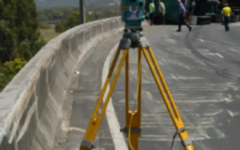
1.2. Instrumentation:
It consists of an EDM, Theodolite, Microprocessor combined into one. It also has a memory card to store the data. It also consists of battery socket which houses the battery. A fully charged battery works for about 3 to 5 hrs continuously.
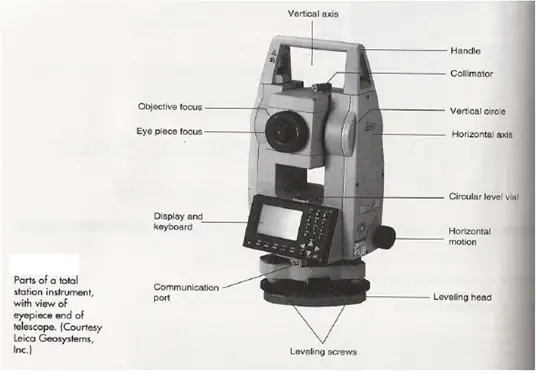
Figure 1: Different Parts of Total Station
1.3. Accuracy of a Total Station:
Accuracy depending upon the instrument and varies from instrument to instrument
1.The angular accuracy varies from1″ to 20 ″.
2.Distance accuracy depends upon two factors.
Instrumental error which ranges from
+ / – 10mm to + / – 2mm.
b) Error due to the length of measurement.
It can be from + / – 10mm to + / – 2mm per kilometre.
1 prism, 2.5–2.7 km2 prisms
5-7 km3 prisms
10-12 kmNIKONOne second+ / – 2mm/km or 2ppmTriple the number of prisms double the distance.LEICAOne second SOKKIAOne second.
1.3.1. Accuracy & Precision
• Precision is the reproducibility of the measurement.
• Accuracy is how close the measured position is to the actual location
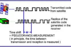
Measurement of distance is accomplished with a modulated microwave or infrared carrier signal, generated by a small solid-state emitter within the instrument’s optical path, and reflected by a prism reflector or the object under survey. The modulation pattern in the returning signal is read and interpreted by the onboard computer in the total station. The distance is determined by emitting and receiving multiple frequencies, and determining the integer number of wavelengths to the target for each frequency. Most total stations use purpose-built glass Porro prism reflectors for the EDM signal, and can measure distances to a few kilometers. Reflectorless total stations can measure distances to any object that is reasonably light in color, to a few hundred meters.
Principle:
Given the co-ordinate of the instrument position and bearing of a backward station the co-ordinates of any other point can be computed.
1.3.2. Total station can be used
- When two points are given.
- When only one co-ordinate is given. In this case the coordinate of the back station is determined by any suitable method.
- When no co-ordinates were given in which case arbitrary system of coordinates can be used.
These devices, also called electronic Tachometers, can automatically measure horizontal and vertical angles as well as slope distances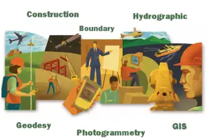 from a single set up. From these data they can instantaneously compute horizontal and vertical distance components, elevations, and coordinates, and display the results on LCD. They can also store the data, either on board or in external data collectors. If the coordinates of the occupied station and a reference azimuth are input to the system, the coordinates of the sighted point are immediately obtained. This information can be directly stored in an automatic data collector, there by eliminating manual recording. These instruments are of tremendous value in all types of surveying. Total Stations offer many advantages for almost all types of surveying. They are used for topographic, Hydrographic, cadastral, project and construction surveys.
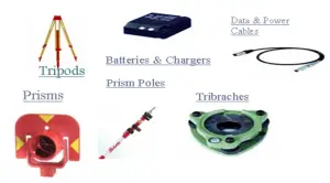
1.4. Accessories for Total Station
With approximately more than 40 different models are available to choose, they are currently the dominant instrument in surveying.
The EDM instrument component installed in a Total Station is relatively small but still has distance ranges adequate for most work. Lengths up to about 2 km can be measured with a single prism, and up to about 6 to 7 km with triple prism.
The angle resolution of available Total Stations varies from as low as a half-second for precise instruments suitable for control surveys, up to 20″ for instruments made specifically for construction stakeout .
1.5. Functions Performed By Total Stations
Total Stations, with their micro processors, can perform a variety of functions and computations, depending on how they are programmed. The capabilities vary with different instruments, but some standard computations include:
- Averaging multiple angle and distance measurements.
- Correcting electronically measured distances from prism constant, atmospheric pressure, and temperature.
- Making curvature and refraction corrections to elevations determine by trigonometric levelling.
- Reducing slope distances to their horizontal and vertical components.
- Calculating point elevations from the vertical distance components (supplemented with keyboard input of instrument and reflector heights).
- Computing coordinates of survey points from horizontal angle and horizontal distance.
- Averages multiple angle measurements.
- Averages multiple distance measurements.
- Computes horizontal and vertical distances.
- Corrections for temp, pressure and humidity.
- Computes inverses, polars, resections.
- Computes X, Y and Z coordinates.
1.6.Operation of Total Station
Because the Total Station contains delicate electronic components they are not as rugged as ordinary Theodolite. They must be packed and transported carefully, handled gently and carefully removed form their cases.
The setting of Total Station over the station mark is similar to an ordinary Theodolite. This includes
- Centring
- Levelling
- Removal of parallax
Total Stations are controlled with entries made either through their built-in keyboards or through the keyboards of hand-held data collectors.Details for operating each individual total station vary somewhat and therefore are not described here.
The accuracy achieved with total station is mainly depends on operator procedure of Careful centering and levelling of the instrument
- Accurate pointing at targets.
- Taking averages of multiple angle measurements made in both direct and reverse positions
Peripheral equipment that can affect accuracy includes
- Tribrachs
- Optical plummets
- Prism and
- Prism poles
Tribrachs must provide a snug fit without slippage. Optical plummets that are out of adjustment cause instruments to be set up erroneously over the measurement point. The prism poles should be perfectly vertical and prism should be well fitted on that. Prisms should be checked frequently to determine their constants.
1.7. Remotely Operated Total Station (ROBOTIC)
The remote positioning unit (RPU) enables control of a total station instrument from a distance
Robotic total stations allow the operator to control the instrument from a distance via remote control.Robotic systems offer reflector less measurement superior to any other instrument available – capable of precision measurements this technology has tremendous benefits for every user. This eliminates the need for an assistant staff member as the operator holds the reflector and controls the total station from the observed point. The remote positioning unit, which is attached to a prism pole, has a built-in telemetry link for communication with the total station. Even a person is not needed near the total station. The Total station automatically moves and locates the target. A person is required at the target at different survey locations. The Robotic Total stations speed up the survey work and reduce the manpower. Robotic total station is the latest, most advanced system on the market today that boasts a new modern design, faster motors, 2000 meter reflectorless range. Available in 1, 3, and 5 second angle accuracies, you can select the instrument that best fits your requirements.
1.7.1. Features Include:
- Innovative, completely cable-free system design.
- New RC-3 with Superior XTRAC™ Quick-Lock tracking technology.
- The most advanced, longest range, and most powerful reflector less technology available.
- Full-color, graphical Windows Mobile instrument & field controller interface.
- Lighter weight than the competition.
1.8. Applications of Total Station
There are many other facilities available, the total station can be used for the following purposes.
- Detail survey i.e., data collection.
- Control Survey (Traverse).
- Height measurement (Remove elevation measurement- REM).
- Fixing of missing pillars (or) Setting out (or) Stake out.
- Resection.
- Area calculations, etc.
- Remote distance measurement (RDM) or Missing line measurement (MLM).
1.8.1. Data Collection Option
Measurements can be stored “on board” with all the total stations. The two options that are available are
- Data can be stored directly in the memory of the microcomputer, and later downloaded to an external storage device via a RS – 232 connections.
- The second option is the removable memory card. When one card is full, it can be removed and another card can be quickly installed.
1.8.2. Detail Survey
Given two points whose coordinates are known, a total station can be used to get the coordinates of various other points based upon those two co-ordinates. Care should be taken that the new points survey are carefully coded. The Map of the area can be obtained after downloading and processing.
1.8.3. Control Survey / Traverse:
It is similar to any type of EDM Traverse.
Definition of Traverse: –
Traverse is the method of control survey in providing horizontal and vertical controls along a pre-defined route by means of establishing a series of connected lines joining the traverse stations.
1.8.4. Traverse:
- In traverse a number of connected survey lines form a framework of survey.
- The direction and length of survey lines are measured with the help of an angular measuring device (Theodolite) and distance measuring device ( Tape, chain, EDM, GPS etc.).
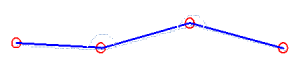
Figure 1: Traverse
1.8.5. Classification of Traverse (Based on accuracy & Based on Instrument used ):
- Based on accuracy
- Primary traverse: accuracy 1:50,000 (Instrument: T3 and invar wire)
- Secondary traverse: accuracy 1:20,000 (Instrument: T3 and EDM)
- Tertiary traverse: accuracy 1:1000 (Instrument: T2 and Chain)
1:2000 (Instrument: T2 and Steel Band)
- Based on Instrument used
- Chain traverse
- EDM traverse
- Plane-table traverse
1.8.6. Classification of Traverse:
- Open traverse: Starts from a known control point and ends at unknown point.
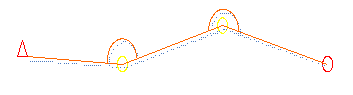
Figure 2: Open Traverse
- Closed traverse: Starts from and ends at known control points.
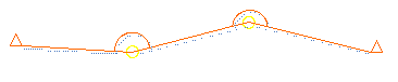
Figure 3: Closed Traverse
- Closed Circuit traverse: Starts from and ends at known control points.

Figure 4: Closed Circuit Traverse
1.8.7. Application of traverse
- Providing control points for large scale surveys.
- Boundary surveys
- Fixing route of a river, road, canal accurately.
- Project surveys.
- Alignment surveys and many more.
- True North i.e. Meridian line
- Grid North line
- Magnetic North line
- Any arbitrary reference line.
1.8.8. The reference line may be:
Azimuth:
- Azimuth of any survey line or traverse leg is the clockwise angle from True North.
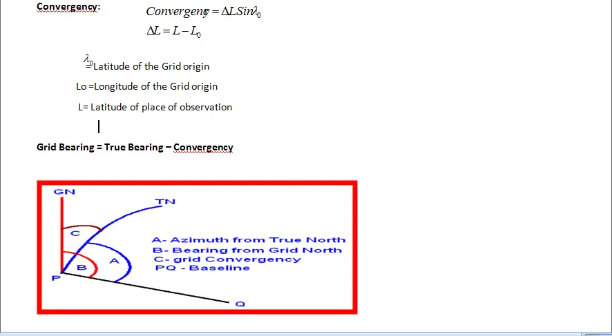
Grid Bearing:
- Grid Bearing of any survey line or traverse leg is the clockwise angle from Grid North.
Magnetic Bearing:
- Magnetic Bearing of any survey line or traverse leg is the clockwise angle from Magnetic North.
1.8.9. Azimuth and Grid Bearing:
- Azimuth can be obtained by astronomical observations.
- Azimuth can be computed by Latitude and Longitude (Spherical coordinates).
- Grid Bearing can be obtained by astronomical observations by applying Convergency.
- Grid Bearing can be computed by Grid coordinates.
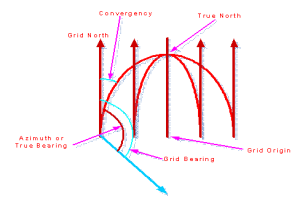
Figure 5: Azimuth and Grid Bearing
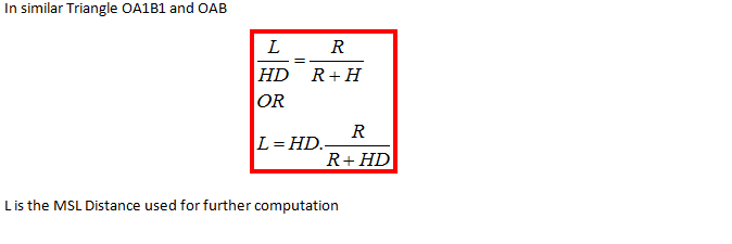
1.9. Remote Elevation Measurement (REM)
The process of finding the height of objects without actually going to the top of the object is known as Remote Elevation Measuring (REM) i.e., a total station placed remotely (faraway) from the object is used to measure the heights.
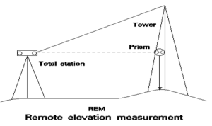
Figure 6: Remote Elevation Measurement
Method: The prism is kept at the base of the object sight the telescope to the prism, and measure the slope distance ‘d’, now tilt the telescope up-to the tip of the object. The height of the object is displayed, from the bottom of the prism depending upon the instrument.
This feature measures the elevation of a point where a prism can not be placed directly. The measurement is extended along the plumb line while the elevation is continuously displayed.
Remote Elevation Measurement:
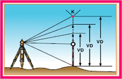
Figure 7: Remote Elevation Measurement
1.9.1. Remote distance measurement (RDM) or Missing line measurement (MLM):
The process of finding the distance between two points A & B (which are not inter-visible from each other) from another point ‘I’ (instrument position) is known as RDM.
This method is very useful for finding distances between two points which has an obstruction between them. It is of two types:
- Continuous
- Radial
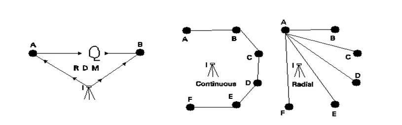
Figure 8: Remote Distance Measurement
Distances can be obtained either in the continuous mode i.e., AB, BC,CD, DE,EF etc., or in the radial mode i.e., AB,AC,AD,AE,AF etc., however, the field procedure is same for both only the selection of operation varies. This is required when there are obstructions in between survey line.

Figure 6: Missing Line Measurement
1.9.2. Fixing of missing pillars (or) Setting out (or) Stake out:
The process of fixing missing pillars on the ground using its theoretical coordinates is known as STAKE OUT. Here two other known coordinates are required.
- Process of finding the positions of known coordinates points e.g. missing boundary pillars.
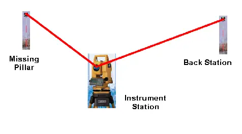
Figure 7: Stake Out
1.9.3. Resection:
The process of finding the coordinate of the instrument position making use of other control points (points whose coordinates are known) is known as RESECTION.
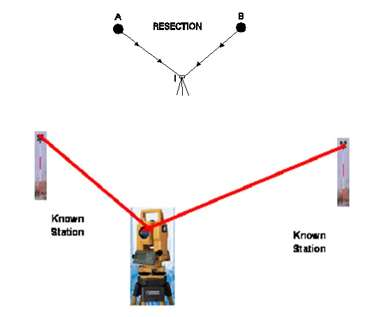
Figure 8: Resection
1.9.4. Area Calculation:
Area can be computed of any figure just by giving the coordinates of the corner of the figure.
- Area Calculation.
- Process of finding the area of a closed figure.

Figure 9: Area Calculation
1.9.5. Uses of Total Station
The uses of Total Station are as follows:
- Mine Survey
- Cadastral Survey
- Engineering Survey
- Large Scale Survey
- Road / Rail / Canal Survey
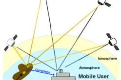
Some total stations also have a GNSS interface which combines the advantages of these two technologies (GNSS – line of sight not required between measured points; Total Station – high precision measurement especially in the vertical axis compared with GNSS) and reduce the consequences of each technology’s disadvantages (GNSS – poor accuracy in the vertical axis and lower accuracy without long occupation periods; Total Station – requires line of sight observations and must be set up over a known point or with line of sight to 2 or more points with known location).
Also Read – What is GLONASS?


I love this article!
very nice important surveying idea
Thanks for sharing this article. Top quality total station survey instruments, packed with advanced features, are available at Skippertech – leading supplier of the positioning technology tools, manufactured by the global leader-Topcon. Other solutions such as GNSS receiver, automatic levels, robotic total stations are also available at reasonable prices. To know more, please visit the official website.
thanks for shering article